Confirm Goods
1 × Top Enclosure (Aluminium)
1 × Base Enclosure (Aluminium)
1 x Weight
1 × Plate (Anodized Aluminium or PVD Coated Brass)
1 × Wilba.tech WT65-XT or WT65-XTX PCB
1 × Wilba.tech WT-USB-C extension PCB
8 × RW Black M3×8 FT T10 Fixtures (Case)
8 × RW SS M3x6 FT T10 Fixtures (Weight)
4 × RW SS M2×4 FT T10 Fixtures (Daughterboard)
8 × RW SS M2×3 FT T10 Fixtures (Hotswap PCB Only)
8 × RW SS M2×3 CSK FT T6 Fixtures (Hotswap PCB Only)
8 × RW SS M2×3.5 Spacers (Hotswap PCB Only)
1 × Set of Zenith Feet
1 x Set of Poron Strips (12 strips)
1 × XO Switchpuller
1 × RW T10 Torx Tool
1 × RW T6 Torx Tool
1 × RW Black Metal End USB-C to USB-A braided cable (USB 3.0) - 1.5m
1 × Various Packaging
Sub-assembly
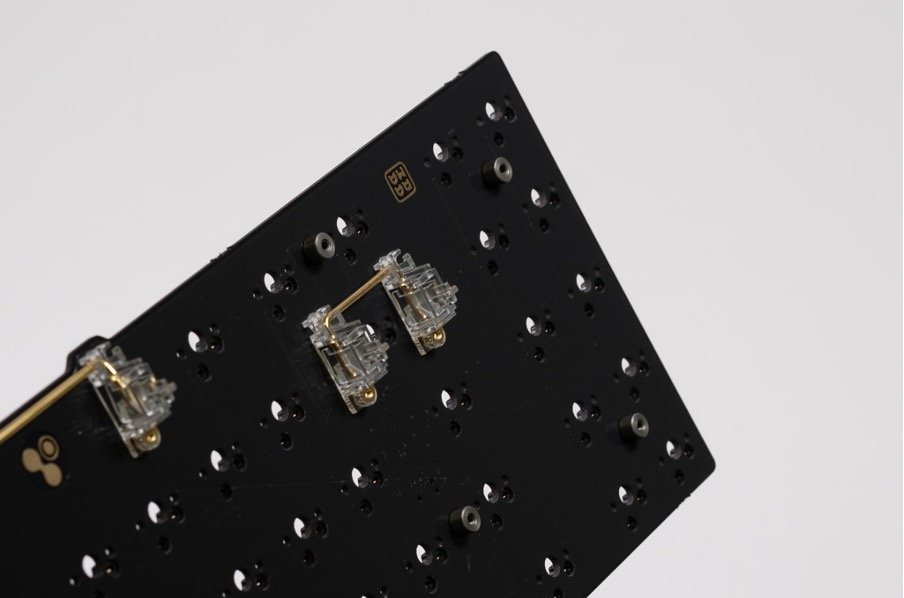
Install stabilisers onto the PCB

2. Secure M2x3 FT T10 screws on the underside of the PCB and have the M2x3.5 spacers tightened on the same side of the PCB where the stabilisers are installed.
3. Align the plate with the PCB, spacers and stabilisers and secure it with 8 of the provided M2x3 CSK FT T6 screws to the spacers. These screws should sit flush into the plate.


4. Put in your desired switches (south-facing) and push it in towards the plate with enough force that it clicks and is secure.


5. (Optional)
Here you can choose to put on your favourite keycap set, or you can do this as the final step.
HOUSING
Unscrew all 8 M3x8 FT T10 screws to separate the bottom and top housing

2. Use the 6 of the Poron strips to place it on the bottom and top housing as shown below.
3. Unscrew all 8 of the M3x6 screws to separate the bottom housing and bottom weight.

4. Open the supplied PCB and disconnect the daughterboard and JST cable.

5. Fasten and secure the daughterboard to the bottom housing as shown, with the USB-C connection facing towards the housing using the M2x4 FT T10 screws

(For the next three steps, we have found it easiest to place the weight on a surface and drop the bottom housing onto the bottom weight for installation.)
6. Connect the JST cable to the daughterboard and feed it towards the gap to reach the other side of the bottom housing.
7. Secure the weight to the bottom housing, making sure that the JST cable sits securely in the channel that is in the bottom weight. Repositioning of the JST cable’s black tube may be required to allow the cable to rest in the channel allowing the bottom weight to sit flush.
8. Once it is flush, use the M3x6 FT T10 screws to secure the weight with the bottom housing.

9. Connect the other end of the JST cable back to the sub-assembly and align it with the bottom housing.


10. Place the top housing on and use the M3x8 FT T10 screws to fasten the top and bottom housing together.


11. Apply the ZENITH feet on the bottom housing.

12. Install your chosen set of keycaps (if you have not done so already).

13. That’s it!
Enjoy using your keyboard and if there are any issues, please reach out to us at support@rama.works!