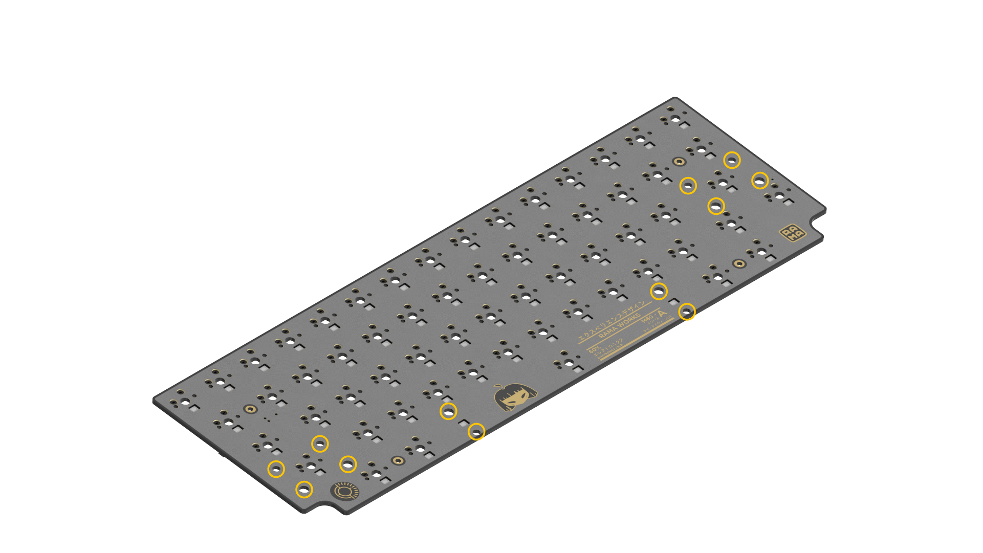
Installing stabilisers, PCB and Switches into the m60—a
First identify the 12 stab holes. Note that the bottom 7U spacebar stabiliser is rotated 180 degrees.
For details on the tools required for the internal screws, see the guide here:
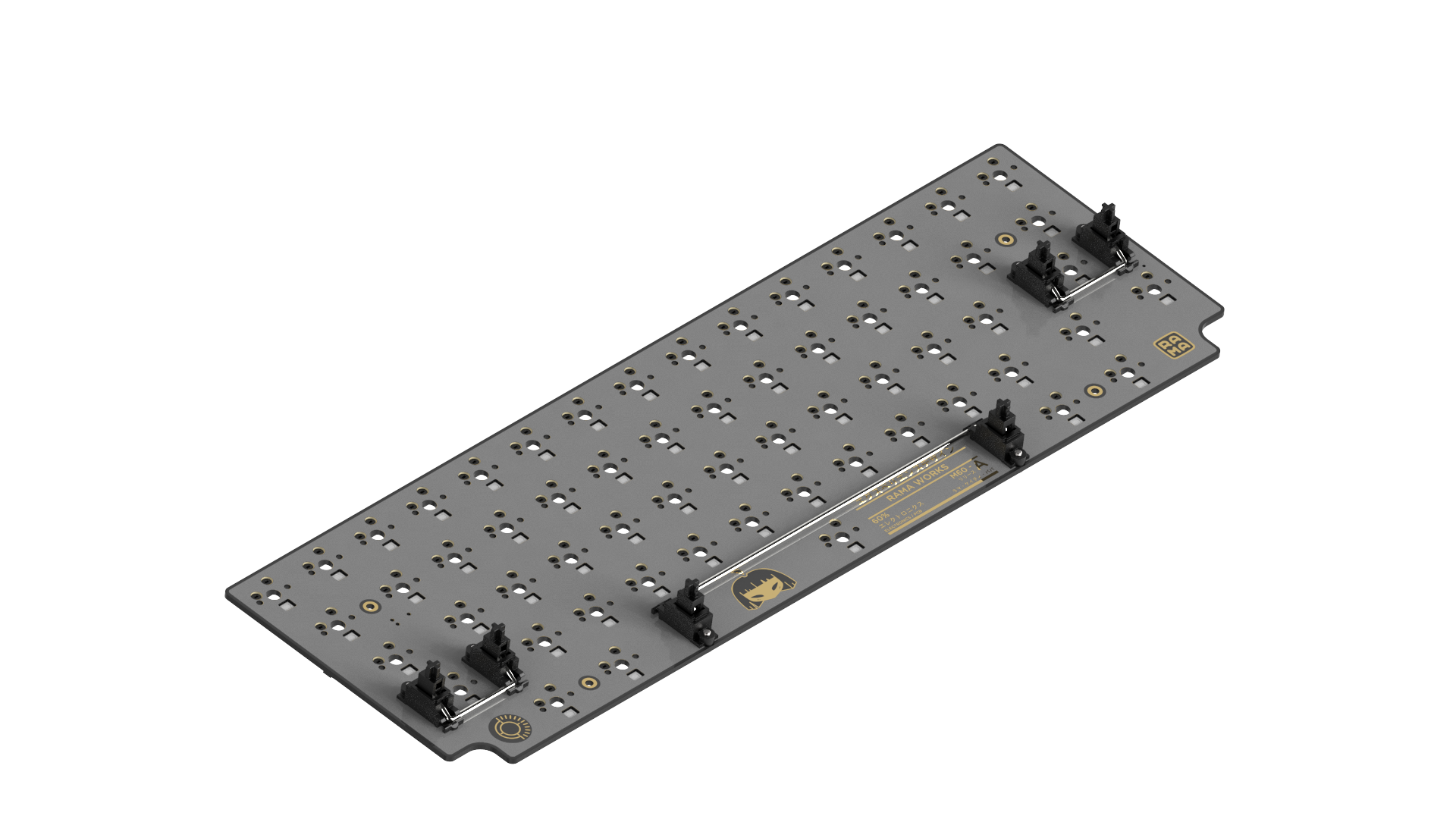
STEP 1
Insert the the stabilisers with the clip in the larger hole first then pivot the stabiliser downwards and push in.


If the stabiliser type is a screw-in, FLIP the PCB then screw the stabiliser in.

Install all 3 stabilisers for the PCB, 2 x 2U Stabilisers for the shift & enter key. And a 7U stabiliser for the spacebar (note it’s rotated 180 degrees).
STEP 2
Before installing the PCB into the unibody enclosure, you may wish to test and validate the PCB by inserting the switches directly to the PCB first as pictured below. You can test your keyboard by using this handy tool located at: https://elitekeyboards.com/switchhitter.php
If keypresses do not register, consult our other guides.

Test the switches in a few different locations, then remove and continue with assembly.
Screw the PCB into the unibody top-frame in the 4 highlighted locations. Note that these screws are for positioning only.
From SEQ2 (and onwards) the PCB utilizes 6 locations for screwing in the PCB, screw in all 6, then, once the switches are installed, remove the middle 2 screws and use them for the U1-C daughterboard PCB.

STEP 3
Start by inserting the switches in the middle of the plate and work your way outwards. For the first few switches inserted in the center, aid by softly pushing the hotswap (not any other components) towards the plate as you insert the switch. Make sure to keep the switch pins completely flat and insert the switch flat.

Pictured: Underside of a Kailh BOX switch, other switches such as ones from Cherry or Gateron will look different but the pin location will remain the same. Note that the pins are straight.

Then continue to insert the rest of the switches.

Before continuing to STEP 4 test the switches and if there any issues follow the guide here:
STEp 4
Screw in the U1-C daughterboard and connect the cable between the two PCB’s.

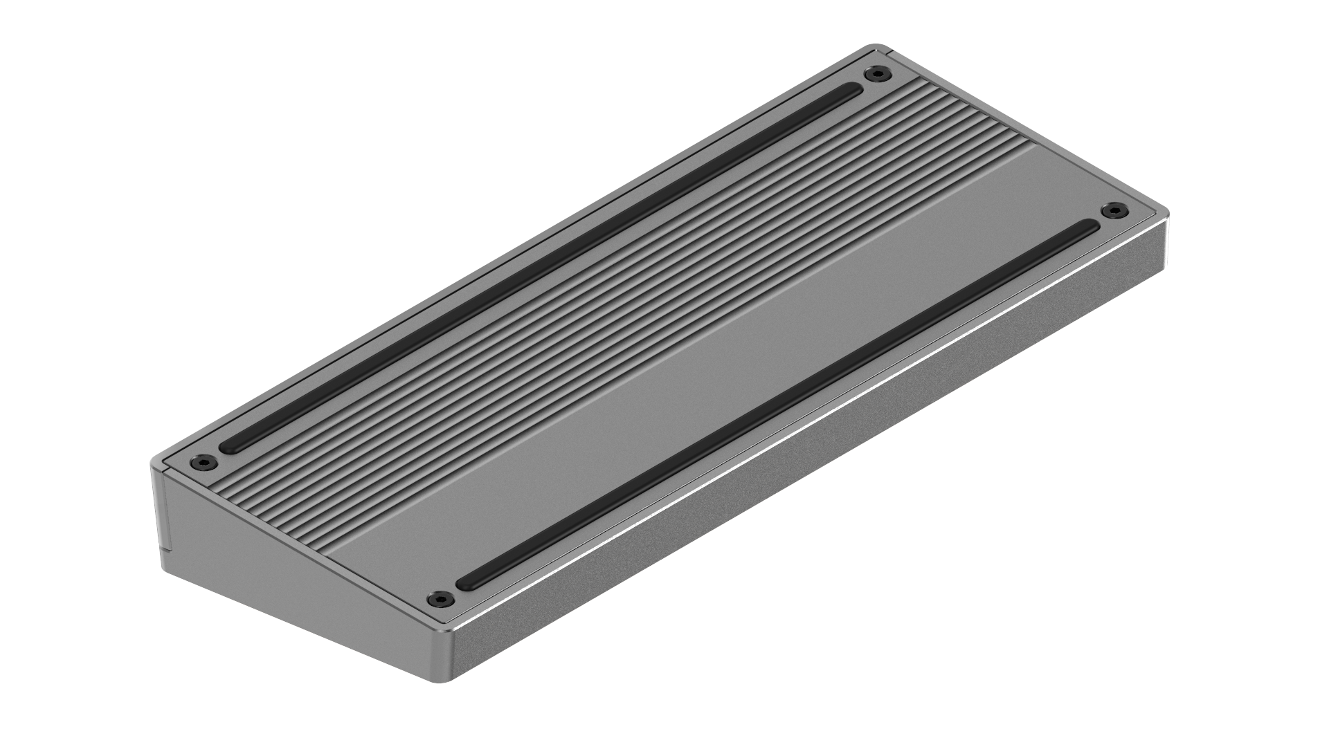
Step 5
Rotate the board, screw in the base with the included 3mm Hex Tool.
STEP 6
Finish off the board by placing on your chosen keycap set!
